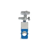
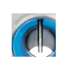
The VACOMASS® elliptic diaphragm control valve is a technically optimized sliding gate control valve with gas-tight shut-off and a lenticular/ elliptical control aperture. It is used for precise and low-loss control of air flow and distribution in the aeration tanks of a wastewater treatment plant. The valve has a falling flow axis to achieve sensitive control of normal and tangential flows (e.g. after elbows), and is designed according to DIN EN 60534-2-3.
The control valve body consists of two halves that are designed to be of wafer or end-of-line type. The inner surface has a groove for a PTFE/ carbon gasket that makes the valve gas-tight and serves as an external guide for the valve´s knife-edge sliding gate. The combination of stainless steel on Teflon/carbon allows precision movement of the plate without vibrations or jamming. A wave breaker in the outlet area of the valve body (patent pending) prevents high-pitched noise generation.
Within the usual control range the valve has a stable control curve, and it can be used from 0-100% stroke. It is designed to have a pressure loss of less than 10 mbar at full load and 100% stroke. The design stroke in control mode typically ranges between 30 – 70%, pressure drop will range between 8-15 mbar (technically required for a stable control and distribution of aeration air at stable and optimum boundary conditions – same pressure conditions related to water depth, aerators etc.).
Air flow rate can be increased significantly and easily for cleaning of aerators (air bumping, flexing) and/or pulse aeration in nitrification zones without mixer during non-aerated process phases by increasing the stroke up to 100% without increase of header pressure. This control valve complies with the requirements of the new standard paper of German Water and Wastewater Association M 229-1, published in September 2017 regarding pressure drop and related energy efficiency.
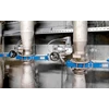
Depending on local pipe situation, there are two different types of measuring and control pipe section possible:
Compact System: The VACOMASS® air flow meter can be installed 500 mm in front of the VACOMASS® elliptic diaphragm control valve. Simultaneous flow profile correction for very precise flow measurement is applied based on actual stroke of the valve. If necessary, piping related disturbances of the flow profile can be examined and compensated during calibration in Binder´s CAMASS® Calibration Lab.
Separated system: If there is sufficient straight pipe run (depending on the type of pipe fittings and the geometry of the pipe run, a minimum distance of 10*D upstream of the VACOMASS® flow meter), the flow meter can be installed at least 5*D in front of the VACOMASS® elliptic diaphragm control valve. Standard calibration can be applied, flow profile correction is not necessary. The total length of the measurement and control section is much longer and in most cases not available.


